Check Bernoulli’s equation for its validity LAB
Lab: Bernoulli’s Theorem Demonstration
Test site:
UDC, engineering building, C level
Lab Objective:
The objectives of the test are to check Bernoulli’s equation for its validity. We are also measuring a divergent or a convergent tube for flow rates. We will be assessing the total static pressure heads in the tube.
Following equipment are used:
Bernoulli’s Theorem Demonstration apparatus
F1-10 Hydraulics bench
F1-15 Bernoulli’s test apparatus
Stopwatch
Theory and introduction:
The mechanics of three kinds of fluids i.e. gases, liquids and plasma are studied in the field of Fluid mechanics which is an important branch of physics. There are different types of forces that are studied in fluid mechanics. These force act upon the three fluids.
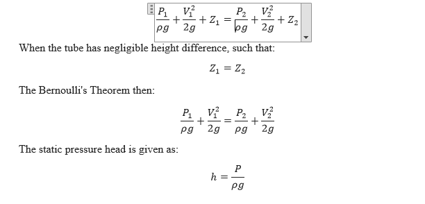
Bernoulli’s Theorem is really important in terms of it providing a basic understanding to the energy and work conservation law. In a closed tube which has fluids moving through it, the total energy remains conserved. The sum of all energies are identified with the following equation:

Test Procedure:
The apparatus is placed on a solid surface and levelled. The Bernoulli apparatus is fitted upon a hydraulic bench so that the base is horizontal. The test section should have tapered section of 14 degrees converging in the flow direction. At this point we are ready to attach the water inlet and outlet. The outflow tube is place above the volumetric tank. The inlet is then attached to bench supply. The hydraulic bench valve and the flow control valve of apparatus are closed and the pump is started. Now open up hydraulic bench valve slowly to fill up the test rig. Close the valve to get air bleed from the tapping point. Now connect a tube having small bore from valve to volumetric tank. Tighten the bleed screw and partly open the hydraulic valve. Now open the air bleed screw to allow air to enter the manometers top and again tighten it when a suitable height is achieved. The maximum flow rate is determined by using the minimum and maximum reading on the manometer scale.
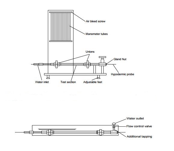
Fig 1: Bernoulli’s Theorem Demonstration Apparatus
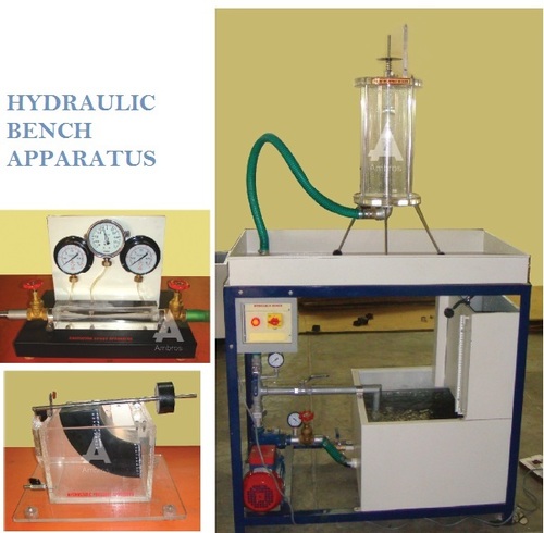
Fig 2: Hydraulic bench apparatus
Data and Calculations:
Equipment Specifications:
| Tapping Position | Manometer Legend | Diameter (mm) |
| A | h1 | 25 |
| B | h2 | 13.9 |
| C | h3 | 11.8 |
| D | h4 | 10.7 |
| E | h5 | 10 |
| F | h6 | 25 |
Flow No 1:
| Volume Collected V (m3) | Time to collect t (sec) | Flow rate (Qv) | Distance into Duct (m) | Area of duct A (m2) | Static head h
(m) |
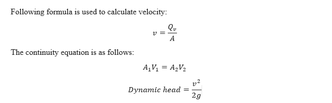
Velocity v (m/s) | Dynamic head
m |
Total head h° (m) | |
| 0.004 | 49.6 | 8.06e-5 | h1 | 0.0 | 490.9e-6 | 0.175 | 0.164 | 0.00137 | 0.176 |
| 0.004 | 49.6 | 8.06e-5 | h2 | 0.0603 | 151.7e-6 | 0.160 | 0.531 | 0.0143 | 0.174 |
| 0.004 | 49.6 | 8.06e-5 | h3 | 0.0687 | 190.4e-6 | 0.144 | 0.736 | 0.0276 | 0.172 |
| 0.004 | 49.6 | 8.06e-5 | h4 | 0.0732 | 89.8e-6 | 0.130 | 0.896 | 0.0419 | 0.172 |
| 0.004 | 49.6 | 8.06e-5 | h5 | 0.0811 | 78.3e-6 | 0.104 | 1.02 | 0.0530 | 0.157 |
| 0.004 | 49.6 | 8.06e-5 | h6 | 0.1415 | 490.9e-6 | 0.127 | 0.164 | 0.00137 | 0.128 |
Flow No 2:
| Volume Collected V (m3) | Time to collect t (sec) | Flow rate (Qv) | Distance into Duct (m) | Area of duct A (m2) | Static head h
(m) |
Velocity v (m/s) | Dynamic head
m |
Total head h° (m) | |
| 0.005 | 72.21 | 6.9e-5 | h1 | 0.0 | 490.9e-6 | 0.166 | 0.141 | 0.0010 | 0.167 |
| 0.005 | 72.21 | 6.9e-5 | h2 | 0.0603 | 151.7e-6 | 0.155 | 0.455 | 0.011 | 0.166 |
| 0.005 | 72.21 | 6.9e-5 | h3 | 0.0687 | 190.4e-6 | 0.143 | 0.362 | 0.0067 | 0.15 |
| 0.005 | 72.21 | 6.9e-5 | h4 | 0.0732 | 89.8e-6 | 0.133 | 0.768 | 0.03 | 0.163 |
| 0.005 | 72.21 | 6.9e-5 | h5 | 0.0811 | 78.3e-6 | 0.114 | 0.881 | 0.039 | 0.153 |
| 0.005 | 72.21 | 6.9e-5 | h6 | 0.1415 | 490.9e-6 | 0.132 | 0.141 | 0.0010 | 0.133 |
Flow No 3:
| Volume Collected V (m3) | Time to collect t (sec) | Flow rate (Qv) | Distance into Duct (m) | Area of duct A (m2) | Static head h
(m) |
Velocity v (m/s) | Dynamic head
m |
Total head h° (m) | |
| 0.004 | 51.6 | 7.8e-5 | h1 | 0.0 | 490.9e-6 | 0.100 | 0.159 | 0.00129 | 0.1013 |
| 0.004 | 51.6 | 7.8e-5 | h2 | 0.0603 | 151.7e-6 | 0.08 | 0.514 | 0.0135 | 0.093 |
| 0.004 | 51.6 | 7.8e-5 | h3 | 0.0687 | 190.4e-6 | 0.064 | 0.409 | 0.0085 | 0.072 |
| 0.004 | 51.6 | 7.8e-5 | h4 | 0.0732 | 89.8e-6 | 0.063 | 0.869 | 0.038 | 0.102 |
| 0.004 | 51.6 | 7.8e-5 | h5 | 0.0811 | 78.3e-6 | 0.060 | 0.996 | 0.051 | 0.111 |
| 0.004 | 51.6 | 7.8e-5 | h6 | 0.1415 | 490.9e-6 | 0.131 | 0.159 | 0.00129 | 0.1323 |
Result:
The overall result of the 3 flow rates is:
| Flow # | Volume (litres) | Time (sec) |
| 1 | 4 | 49.6 |
| 2 | 5 | 72.21 |
| 3 | 4 | 51.6 |
Conclusion:
We were able to verify Bernoulli’s theorem for its accuracy and validity with the help of the nearly horizontal tube.
Related Posts
 Key debates in African Diaspora Studies
 Write an essay (350- 400 words) describing a person, place, or object you know well
 How is Impressionism an outgrowth of Realism?
 Factors Influencing the Defense of Human Rights
 In the discussion on the podcast, what role do research ethics, including confidentiality, play
 Improving profitability or efficiency of the business process