Center of Pressure on a Plane Submerged Surface
Lab 3: Center of Pressure on a Plane Submerged Surface
Objectives:
The objectives of this lab are to analyze a plane object and find out its center. The surface of the object can either be totally or partially submerged in liquid. Another objective of this lab test to compare between the locations of center of pressure with respect to centroid.
Introduction:
The point where we apply the hydrostatic force is called the center of pressure. As the object’s surface moves away or towards the liquid, the center of pressure of the object also varies.
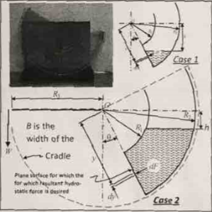
Fig 1: Center of Pressure
Theory:
The above figure illustrated how the center of pressure is measured with the help of an apparatus. It is evident for the figure that a differential force is acting upon a differential are. The equations bellow are used in this regards.
The moment of dF about O in the figure above is:
The above figures presents two cases with objects partially merged and fully merged in the liquid. The following discussion sheds some light on both of the cases one by one.
Case 1:
dF is differentiable from h/cosθ to R2:
When the moment between the same limits equation is integrated, it leads to:
Case 2:
dF is differentiable from R1 to R2:
Integrating the equation for moment between the same limits yield:
The center of pressure in each case could be found by dividing the moment by the force.We divide the moment by the force to find out the center of pressure in both cases.
Following procedure is followed:
It is important to make sure that zero line of back planes is in line with the zero degree line of tank and level the base plate. The counter balance weight is removed to pour in water into the tank at a desired angle. Now hang the hanger of weight and add water to the quadrant tank. Keep adding water until desired angle is achieved. The weight and distance of the water is recorded. More weight and water are added to achieve the exact angle. Record the weight and distance of the water. Add water until we get the specified angle 0˚, 10˚, 20˚ and 30˚. The steps are repeated for all the angles. Repeat the steps for all the angles.
Calculation from different readings and observations:
Inner radius = R1 = 10 cm
Outer radius = R2 = 10 cm
Lever arm = R3 =30 cm
Inside tank width = B =7.5 cm
The Smallest graduation of measure of distance to free surface h = 3.8 cm
| Case # | 0˚ | 10˚ | 20˚ | 30˚ | ||||||||
| Mass hanger (g) | Distance to free surface h (cm) | Cd
(cm) |
Mass hanger (g) | Distance to free surface h (cm) | Cd
(cm) |
Mass hanger (g) | Distance to free surface h (cm) | Cd
(cm) |
Mass hanger (g) | Distance to free surface h (cm) | Cd
(cm) |
|
| 1 | 50 | 15.1 | 4.9 | 108 | 14 | 6.1 | 170 | 14.4 | 4.6 | 268 | 13.8 | 4.1 |
| 70 | 15 | 5.5 | 158 | 12.6 | 7.3 | 220 | 13 | 6.3 | 288 | 13 | 4.9 | |
| 120 | 13.2 | 7 | 208 | 11.6 | 8.6 | 270 | 11.8 | 7.5 | 338 | 11.8 | 6.3 | |
| 170 | 11.8 | 8.2 | 258 | 10.6 | 9.6 | 330 | 10.6 | 8.7 | 358 | 11.2 | 6.9 | |
| 2 | 270 | 9.6 | 10 | 358 | 9.8 | 10 | 470 | 8 | 10 | 658 | 6.2 | 10 |
| 320 | 8.6 | 10 | 408 | 8 | 10 | 520 | 7 | 10 | 698 | 5.4 | 10 | |
| 370 | 7.8 | 10 | 458 | 7 | 10 | 570 | 6 | 10 | 740 | 4.8 | 10 | |
| 470 | 5.8 | 10 | 508 | 5.8 | 10 | 620 | 5.2 | 10 | 790 | 3.8 | 10 | |
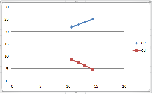
The center of pressure is calculated from the formulas in the table bellow:
| Case # | 0˚ | 10˚ | 20˚ | 30˚ | ||||
| Distance to free surface h (cm) | CP | Distance to free surface h (cm) | CP | Distance to free surface h (cm) | CP | Distance to free surface h (cm) | CP | |
| 1 | 15.1 | 18.37 | 14 | 7.8 | 14.4 | 25.1 | 13.8 | 43.2 |
| 15 | 18.33 | 12.6 | 8.33 | 13 | 23.9 | 13 | 41.4 | |
| 13.2 | 17.73 | 11.6 | 8.7 | 11.8 | 22.9 | 11.8 | 38.8 | |
| 11.8 | 17.27 | 10.6 | 9.1 | 10.6 | 21.9 | 11.2 | 37.5 | |
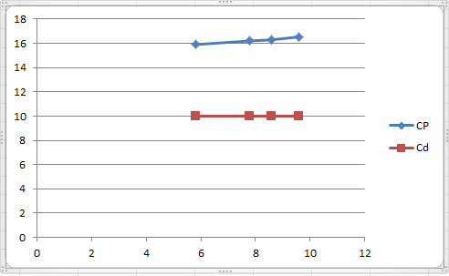
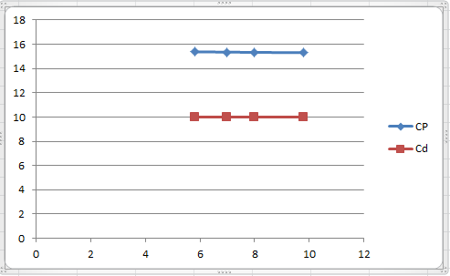
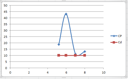
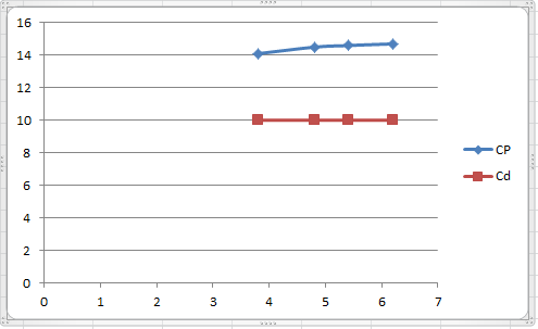
| 2 | 9.6 | 16.54 | 9.8 | 15.31 | 8 | 13.19 | 6.2 | 14.7 |
| 8.6 | 16.3 | 8 | 15.33 | 7 | 11.1 | 5.4 | 14.6 | |
| 7.8 | 16.2 | 7 | 15.35 | 6 | 43.1 | 4.8 | 14.5 | |
| 5.8 | 15.9 | 5.8 | 15.38 | 5.2 | 18.7 | 3.8 | 14.1 | |
Graphs: Graphs for different cases have been shown as follows:
Case 1:
For 0˚:
For 10˚:

For 20˚:
For 30˚:
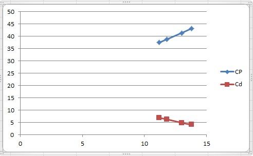
Case 2:
For 0˚:
For 10˚:
For 20˚:
For 30˚:
Results
The finds of the experiment suggest that for each angle of inclination, the center of pressure falls above the centroid. The coincidence point is at 10 degree where the object is partially submerge while it is fully submerged at 20 degree.
Related Posts
 Independent Analysis A Framework for Treating Cumulative Trauma With Art Therapy. Art Therapy, 31(2), 79-86.
 Five-forces model and a firm’s international business strategy
 What is ethics? Why is ethics important to the study of international management?
 Define credibility
 IR CASE STUDY
 Analytical Summary Article : Trauma, PTSD, and Resilience A Review of the Literature. Trauma, Violence, & Abuse